
#evpn #multi-homing #srlinux
Hi there, long time no see 🙂
I’m back with a topic that kept me busy lately.
Until recently, I assumed that the EVPN and its capabilities would be well received as a known standard. But lately, I have noticed ‘again’ that new things do not spread so fast in the real world!
EVPN has many advantages, including the built-in multi-homing (MH) capability, which is standards-based and defined by RFCs (7432, 8365). However, the existing proprietary solutions from different vendors are still widely used. One of the main reasons I could see is that EVPN MH is perceived as a complex solution.
Well, I’ll try to do something about that 🙂
This post covers EVPN MH terminology and how it is implemented in an EVPN-based SR Linux data center fabric built with the containerlab.
If you don’t have an experience with containerlab or SR Linux yet, please check the previous posts on how to build a lab and configure it with EVPN.
No time for that? You’ll get a link somewhere in this post to a pre-build containerlab files to be deployed in your Linux machine.
Let’s start!
EVPN Multi-homing Terminology
The SR Linux implements standard EVPN multi-homing, so the terminology I explain here is pretty much identical in any vendor;
- MAC-VRF: A layer 2 broadcast domain in SR Linux. The sub-interfaces of multi-homed CE are typically connected to the same MAC-VRF in different PEs.
- Multi-homing Modes: There are two modes defined by standard;
single-activeandall-active. The single-active has only one active link while all-active uses all links and provides load balancing.
- Ethernet Segment (ES): Defines the CE links connected to multiple PEs. Each ES has a unique identifier (ESI) known EVPN network-wide which used to prevent duplication.

Sub-interfaces of these physical interfaces can be attached to different MAC-VRFs. - Link Aggregation Group (LAG): LAG is needed for all-active but optional for single-active multi-homing.
Now we know what to configure for a multi-homed CE in an EVPN-based network.
Let’s get one in the lab!
EVPN L2 Multi-homing Configurations
The below items to be configured in all PEs that provide multi-homing to a CE.
- A LAG and member interfaces
- Ethernet-segment
- MAC-VRF – Interface association
Before configuring these, the underlay connectivity, BGP EVPN and MAC-VRF must be configured.
If you prefer a pre-configured lab, just clone this one:
# git clone https://github.com/aaakpinar/NCE.gitCheck out the details of the SR Linux generic lab!
LAG Configuration
Let’s start with the interfaces and the LAG configuration in both leaf1 and leaf2.
We try to get something like this:
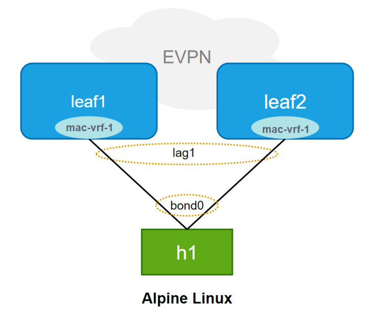
First, let’s get the LAG interface configured. This is mandatory for all-active multi-homing mode.
Below we created the lag1 and enabled it with the vlan-tagging so that this LAG can get multiple subinterfaces and be assigned to different MAC-VRFs:
A:leaf1# interface lag1 admin-state enable
A:leaf1# interface lag1 vlan-tagging true
And create a subinterface to be added under the MAC-VRF:
--{ * candidate shared default }--[ interface lag1 ]--
A:leaf1# info subinterface 1
    subinterface 1 {
        type bridged
        vlan {
            encap {
                untagged {
                }
            }
        }
    }
Also, the lag-type is configured as LACP. The LACP parameters must match in all nodes, leaf1 and leaf2 in this case:
--{ * candidate shared default }--[ interface lag1 ]--
A:leaf1# info lag
    lag {
        lag-type lacp
        member-speed 10G
        lacp {
            interval SLOW
            lacp-mode ACTIVE
            admin-key 11
            system-id-mac 00:00:00:00:00:11
            system-priority 11
        }
    }
In the end, whole lag1 configuration would be like:
A:leaf1# info interface lag1
    interface lag1 {
        admin-state enable
        vlan-tagging true
        subinterface 1 {
            type bridged
            vlan {
                encap {
                    untagged {
                    }
                }
            }
        }
        lag {
            lag-type lacp
            member-speed 10G
            lacp {
                interval SLOW
                lacp-mode ACTIVE
                admin-key 11
                system-id-mac 00:00:00:00:00:11
                system-priority 11
            }
        }
    }
The, add interfaces to the LAG:
A:leaf1# info interface ethernet-1/11
    interface ethernet-1/11 {
        admin-state enable
        ethernet {
            aggregate-id lag1
        }
    }
Until here, it is quite similar to a local link aggregation of any vendor. At this point, we’ll create an ethernet segment for leaf1 and leaf2 to sync for this LAG.
Ethernet-Segment Configuration
In SR Linux, an ES is configured under [ system network-instance protocols ] context.
--{ running }--[ system network-instance protocols ]--
A:leaf1# info
    evpn {
        ethernet-segments {
            bgp-instance 1 {
                ethernet-segment ES-1 {
                    admin-state enable
                    esi 01:11:11:11:11:11:11:00:00:01
                    multi-homing-mode all-active
                    interface lag1 {
                    }
                }
            }
        }
    }
    bgp-vpn {
        bgp-instance 1 {
        }
    }
The ethernet-segments are typically created under the bgp-instance 1. The ES identifier (esi) and the multi-homing-mode must match in all leaf routers. And here we add the LAG interface.
The bgp-vpn is also configured to get BGP information (RT/RD) for the ES routes.
MAC-VRF Configuration
And of course, we need to attach the ES/interface to a MAC-VRF.
A:leaf1# info network-instance mac-vrf-1
    network-instance mac-vrf-1 {
        type mac-vrf
        admin-state enable
        description MAC-VRF-1
        interface lag1.1 {
        }
        vxlan-interface vxlan1.1001 {
        }
...
That’s all at the SR Linux (PE) side.
Alpine Host (CE) Configuration
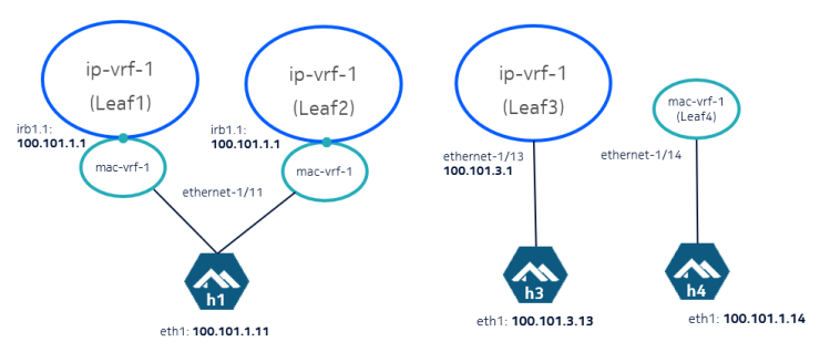
In the lab I referred, you get the below topology already set up:
If you need to configure it yourself, the interface configuration of h1 in /etc/network/interfaces would look like this:
auto bond0
auto eth1
auto eth2

iface eth1 inet manual
bond-master bond0
mtu 1400

iface eth2 inet manual
bond-master bond0
mtu 1400

iface bond0 inet static
address 100.101.1.11
netmask 255.255.255.0
bond-mode 802.3ad
bond-xmit-hash-policy layer3+4
bond-miimon 300
mtu 1400
Ensure the bonding module is loaded (modprobe bonding) on your linux machine!
Here we are!
And finally, let’s send some traffic to the network from the multi-homed CE.
You can run tcpdump to check which interface your traffic is going through, or you can monitor it using the monitor interface.
# monitor interface lag1 subinterface 1 statistics in-packets
Hopefully I’ll get more into the EVPN MH and how it overcomes the challenges of L2 multi-homing connectivity in the next post.
See you in there!
